The loads affecting the rocket during flight cause strains in its structure. The measurement of the occuring strains is relatively simple. The key aspect is to define an appropriate relation between the measured strains and the loads that cause these strains, especially to separate the overall load into the proportions of the six different sectional loads that appear in the measurement plane. These six differnt sectional loads are one normal force Nx, two shear forces Qy and Qz, two bending moments My and Mz and one torsional moment Mx. Fig. 1 visualizes these sectional loads affecting the rocket structure in the measurement plane.

Fig. 1: Definition of the different sectional loads occuring in the measurement plane.
Instead of an analytical calculation to obtain the loads out of the measured strain data - which makes it hard to take into account imperfections in the structure and relies on various assumptions - the HERMESS measurement system follows the approach of the so called Skopinski Method, described more detailed below, which relies on a calibration of the measurement system for the individual structure and use case that should be investigated.
This method of relating measured strain data and flight loads demands the equipment of the inner hull of the rocket module with measurement points, each called STAMP, containing two strain gauge rosettes and one temperature sensor. For more information about these measurement points see signal generation. A number of three STAMPs with a total of six strain gauge rosettes would be enough to make use of the Skopinski Method for data analysis. In order to better capture imperfections in the investigated structure, caused by hatches etc., and to guarantee redundancy in the signal generation a numer of six STAMPs is defined for the HERMESS measurement system in approximately 60° increments at the inner hull of the roket module. The different orientation of the strain gauge rosettes allows the detection of normal and shear distortions.
The Skopinski Method was first introduced in a technical report1 of the National Advisory Committee for Aeronautics (NACA) in the year 1954 with the objective of measuring flight loads in aircraft structures. This method enables the calculation of sectional loads even in-flight, which are not directly measurable. Another big advantage of this method is the fact that it considers all kinds of imperfections of the investigated structure as the measurement system gets calibrated directly with that structure. This fact qualifies the method to be used in addition to an analytical or simulation model which always differs from the original structure in some way because of the mentioned imperfections and other kinds of unexpected material behavior that can not be taken into account by these models.
The basic idea of the Skopinski Method is to apply defined loads on the structure that should be investigated in various scenarios and measuring the corresponding signals of the strain gauge rosettes, that are applied on the structure. As characteristic signal response the change of the signal with increasing load is preferred absolute amplitudes to increase accuracy. By repeating this process applying all kinds of loads that are expected during flight, the correlation between the measured signals and the applied loads that cause that signals gets more precise step by step with every calibration test that is done. In particular, the effect of a variable load application point, as it occurs during the flight due to the induced spin of the rocket, on the relationship between the applied load and the resulting signals of the measuring system shall be investigated. A further component of the calibration procedure is the investigation of combined load cases, e.g. the eccentric application of an axial force, which causes a bending moment in the structure in response to the load in addition to a normal force.
The aim of the calibration procedure is to initialize a so-called calibration matrix, whose elements reflect the sensitivities of the individual strain gauge rosettes with respect to the different sectional loads. This calibration matrix results from a combination of the results of all calibration tests carried out, making use of a least squares method.
The procedure of the calibration of the measurement system in visualized in fig. 2.
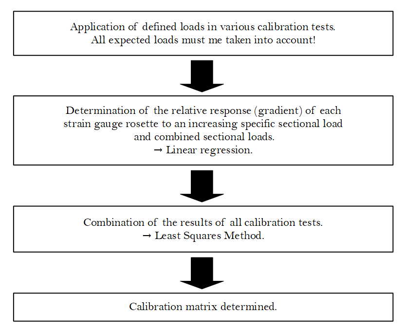 Fig. 2: Calibration process necessary for usage of the Skopinski Method.
Under the assumption of a linear correlation between the measured signals of the strain gauge rosettes and the loads affecting the structure in the measurement plane and further taking into account the principle that in a usual load case all sectional loads occur in the measurement plane the sectional loads can be determined out of the measured signals of the strain gauge rosettes by a simple matrix-vector multiplication with the calibration matrix as a transformation rule, visualized in fig. 3.
The evaluation of the signals recorded by the strain gauge rosettes makes use of the assumption that the rocket structure heats up due to frictional effects in flight without thermal loads arising. This assumption, which presupposes an isotropic material, is further substantiated by an expected uniform temperature distribution over the rocket structure in circumferential direction due to the induced spin and the high thermal conductivity of the structural material aluminium. However, since the measuring system of the applied strain gauge rosettes, the resulting signals of which are each determined by a half-bridge configuration and are thus effectively temperature-compensated, provides increased signals when the temperature of the structure that is investigated is increased compared to a lower defined reference temperature, the temperature of the rocket structure is recorded in the vicinity of the application points in order to carry out a more accurate correction of the temperature influence on the measuring signals of the strain gauge rosettes. This temperature dependant correction of the measured strain data is carried out before making use of the calibration matrix.

Fig. 3: Principle of converting measured strain signals in corresponding sectional loads.
The redundancy of the strain gauge rosettes makes it possible to even convert the measured strain data in the corresponding sectional loads if in case of any failure only one half of the strain gauge rosettes gathers reliable data. In that case the system of equations relating the signals of the six strain gauge rosettes to the six different sectional loads would be unambiguously solvable. For data analysis only the part of the calibration matrix that contains the sensitivities of the rosettes their signals should be converted would be used.

The adverse operating conditions to which the HERMESS measuring system is exposed require the definition of strict requirements for the overall system and its subsystems, which can be roughly divided into functional, performance, design and operational requirements. An extensive verification process is required to ensure that these detailed requirements are met.
The tests to verify the defined system requirements aim at different scenarios. In the course of this process, a vibration test is performed on a shaker test rig, which allows the simulation of different vibration profiles, to check the mechanical load capacity of the measuring system. Especially in the launch phase of a rocket, the structure is exposed to strong vibrations, which is why this flight phase, together with the high accelerations that occur as well as the large attacking air forces at low altitudes, proves to be very critical.
Furthermore, the functionality of the measuring system has to be ensured over a wide temperature and pressure range. The temperature differences between before and some time after take-off can amount to several hundred Kelvin due to the aerodynamic heating of the structure. With increasing flight altitude, the ambient pressure also decreases rapidly, so that it is very close to vacuum conditions already at flight altitudes below 100 km. To verify the operational capability of the measuring system under these ambient conditions, tests are carried out in a thermal-vacuum chamber.
In addition, a series of tests will be carried out to verify the requirements for the components for signal generation and signal processing, the software, as well as the noise and electromagnetic interference behaviour.
1 Skopinski, T. H., Aiken, W. S. Jr., Huston, W. B. (1954). Calibration of strain-gage installations in aircraft structures for the measurement of flight loads. NACA Technical Report 1178. Langley Aeronautical Lab. Langley Field.
This website uses cookies
In order to optimize our website for you and to be able to continuously improve it, we use cookies. In order to be able to fully use the functions of our website, please consent to their use.
Necessary cookies help make a website usable by enabling basic functions such as page navigation and access to secure areas of the website. The website cannot function properly without these cookies.
| Name | Provider | Info | Expiry |
|---|---|---|---|
| cookieinfo | Project HERMESS | Saves the user settings for the cookies. | 90 Tage |
| cms144-session | Project HERMESS | Unique ID that identifies the user's session. | Session |
Preference cookies enable a website to remember information that affects the way a website behaves or looks, such as: B. Your preferred language or the region you are in.
| Name | Provider | Info | Expiry |
|---|---|---|---|
| cms144-language | Project HERMESS | Saves the language version of a website selected by the user. | 90 Tage |
Cookies are small text files that are used by websites to make the user experience more efficient.
According to the law, we can store cookies on your device if they are absolutely necessary for the operation of this site. We need your permission for all other types of cookies.
This site uses different types of cookies. Some cookies are placed by third parties that appear on our pages.
You can change or withdraw your consent from the cookie declaration on our website at any time.
Find out more about who we are, how you can contact us and how we process personal data in our privacy policy.
Please include your consent ID and date when contacting us regarding your consent.